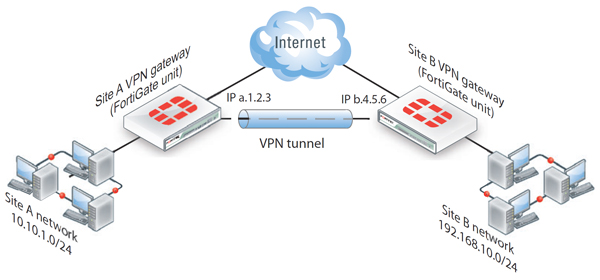
Virtual Private Networking (“VPN”) is a cost effective and secure method for site to site connectivity without the use of client software. Fortinet Fortigate UTM appliances provide IPSec (as well as SSL VPN) “out of the box”. Specifically, IPSec Tunnels can be triggered via firewall rules based policies or interface mode. Interface mode is a more sophisticated and flexible method of providing connectivity between sites due in large part to its seamless integration into the Fortigate’s routing table.
 To begin configuration, follow these steps:
To begin configuration, follow these steps:
1) Open and configure Phase 1 attributes under the VPN|IPSec|Auto Key (IKE) tab via the management console. Be sure to make note of the following parameters:
- After configuring the target IP address, be sure to attach the Phase 1 local interface to your WAN connection (i.e. the interface your ISP uplinks into).
- Either Aggressive or Main Mode will work. If you choose Aggressive it must be configured in the Phase 2 configuration.
- P1 Proposal, typically AES-128 with SHA1 authentication, DH Group 5.
- Keylife 28000 (default works fine)
- Nat Traversal (default enabled)
- Dead Peer Detection (default enabled)
2) Now, configure your Phase 2 attributes, choosing the SAME options in Phase 1. If you are using Aggressive mode, be sure to select your source and destination addresses in the Quick Mode Selector. Note, the default key life of 1800 seconds works in most cases. In the event your site to site VPN is not Fortigate to Fortigate, you should consult your vendor’s recommendations, as this typically hoses Phase 2 establishment.
3) The next crucial step of establishing IPsec interface mode is ensuring correct firewall rules. Here is where you create inbound and outbound rules between the virtual VPN interfaces and your internal network. The trickiness is to read the rule as follows:
- Incoming Interface – this is the VPN interface you named in Phase I.
- Source address – this will be the remote site’s information (you should have named this in Firewall Objects | Address )
- Outgoing Interface – this will likely be your internal network (LAN)
- Destination Address – this will be your local LAN addresses.
- Again, you will need to configure firewall rules in BOTH directions to make this work.
4) Next, you will need to create an address space under the WAN interface (go to Network | Interfaces, then click on the blue arrow to see Tunnel Interfaces). Assign simple /32 addresses for the local and remote Tunnel Interfaces (this will be important for the next step).
- IP: 10.255.1.1 255.255.255.255 Remote IP: 10.255.1.2 255.255.255.255
5) Next step is creating a static route that points to the remote network:
- Destination IP/Mask will be the remote network
- Device will be the Tunnel Interface you named in Phase 1
- Default distance of 10 is fine.
You should be able to see the VPN tunnel established in the IPsec Monitor under the VPN|Monitor section. Additionally, you should be able to ping from local to remote networks. Furthermore, you will see the routes propagated in the Fortigate’s route table.
No comments:
Post a Comment